   |

 |
141 |
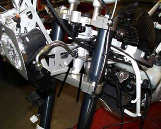
141-142 The installation of the faring mount with the headlamp/oil cooler assembly.
The complete assembly is installed with two M8x50 bolts and four spacers at the front of the head tube. Each bolt has a loop clamp installed as shown. The two oil lines are held in place with the loop clamps on the left and right. On the left the additional tab is installed to secure the oil line in place with an M6x10 bolt and washer. The right side oil line is connected to the oil cooler (17mm wrench), this is the line that connects to the bottom of the motor and is therefore complete. Make sure there is proper clearance for the line while steering all the way to the left and right. If the line is positioned correctly the bracket and cable tie down near the starter can be tightened. The oil line on the left side can now be connected to the cooler. The other end of the line with the reducer can now be installed into the rubber line at the base of the oil tank (return line) and secured with the original hose clamp. |
 | 142 |
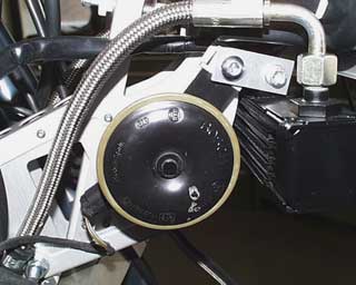 | 143 | Install the horn.
The horn is installed onto the mount with an M8x20 button head (5mm hex) and the original sheet metal nut. The horn is placed on the inside of the mounting bracket. The plug can now be reattached to the horn. |
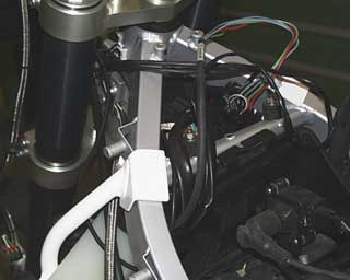
 | 144 | Install the grips, remote switches, levers and hand guards.
The original levers for the clutch and brake will need to be shortened just after the "ball". The remote switches for the IMO and the roadbook are installed after the clutch lever mount and left side combination switches. Then the left side "pro-grip' can be installed. The clutch cable must now run under the coolant tank, between the tank and the radiator. |
 | 145 | Install the hand guards as described in the instructions from Acerbis. Use the special mounting kit for use with the MAGURA x-LINE bars. The grips must be cut open at the ends for the installation of the hand guards. |
 | 146 | The stainless steel brake line is screwed onto the brake master cylinder with a new gasket. The levers are shortened as shown. |
 | 147 | The modification to the throttle with heated grips. The twist grip is removed from the switch housing, pay attention to the pulley position. Remove the cables for the heated grip and carefully cut down the slider.
NOTE: If you do not want to destroy the heated grips, you can get the non-heated slider from your BMW dealer instead. If you are using the MAGURA bars the heated grips cannot be used. |
 | 148 | Place the second "pro-grip" with the lettering facing up, onto the twist grip slider, and reinstall into the switch housing. |
 | 149 | The complete throttle and switch housing can now be installed onto the bars. The throttle cable can be reconnected, along with the shortened brake lever. The mounting plate for the throttle cable can be reattached with the original screw. |
 | 150 | Reinstall the right side combination switch and route the wires along the bars and down through the forks. Cut of the end of the grip and install the right side hand guard. |
 | 151 | The brake line should run parallel to the bars and on the left side run through the two loop clamps we placed onto the fork clamp pinch bolts. Connect the brake line to the caliper using the original hollow banjo bolt and two new gaskets. the banjo bolt is tightened to 9ft/lbs. Fill and bleed the front brake master cylinder per the manufactures specifications. Clamp the brake line and the sensor wire to the fork slider cover. |
 | 152 | The wires for the combination switches on the left and right are laid along side the head tube, and once again routed back through the lower left rear corner of the e-box. The plugs of the left combination switch (orange), ignition, brake light, and clutch switch can all be reattached. The plug for the right combination switch (black) is left loose and will be modified later (step 164-167). The plugs for the heated grips are omitted with the MAGURA bars. |
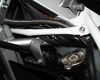 | 153 | The tank mount crossbar is installed from the left side so that all the wires are situated behind it. the crossbar is then bolted to the tank mounts on each side using an M6x20 bolt (5mm hex) two washers and a locknut. Once the crossbar is installed and you have checked for proper clearance while steering both directions, the wires can all be secured with cable ties. |
 | 154 | Assembling the base plate for the cockpit.
(1) The three rubber/metal mountings 15/15 M4 are installed with Phillips head screws M4x8
(2) The two rubber/metal mountings 25/15 M6 are installed with M6x10 countersunk bolts. (4mm hex) |
 | 155 | The IMO 100 is installed with two M4 washers and locknuts. Between the IMO and the aluminum base plate install the polycarbonate bedplate. |
 | 156 | The roadbook holder is installed directly onto the aluminum base plate with four M4x8 button heads (2.5mm hex) and large washers. The bolts are installed from inside the roadbook holder. Secure the screws with Loctite 243. |
 | 157 | The new indicator lamp unit is fastened with two Phillips head screws M4x14 countersunk, and two special countersunk washers, two large washers and locknuts. |
 | 158 | The pre-assembled aluminum base plate is now mounted onto the faring mount with two M6 locknuts and large washers and three M4 locknuts and large washers. |
 | 159 | The original plug for the indicator lamps must be removed from the original speedometer assembly. The two plastic latches on the sides of the plug must be hinged open, then from the front of the plug a small sharp pin must be inserted to release the individual connectors. Release and pull each of the original wires from the plug.
|
 | | Insert the wires of the new indicator lamp assembly into the original plug. If you look closely the plug is numbered where each of the wires goes in. The list below shows the proper installation of the new wires into the plug. When the wires are installed you will hear them click when they are fully into the plug. When all the wires are installed, close the two hinged latches and connect the plug to the matching connector of the wiring harness.
Connector code
1: Aqua                       6: Brown
2: Gray, green, red, yellow   7: Unused
3: Blue                       8: Violet
4: Orange                     9: White
5: Pink 10: Black |
 |