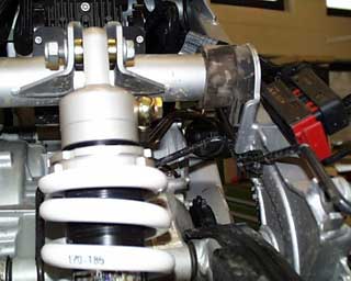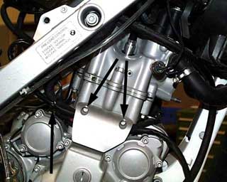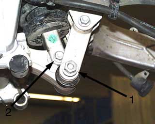
Remove the lower swing arm linkage bolt (1) so the shock bolt can be removed. Be careful with the two dust caps when removing the linkage bolt. Now remove the lower shock bolt. (2)
42
Remove the upper shock bolt. Lift up and remove the shock with the reservoir and the adjuster tank. The swing arm linkage bolt can now be replaced.
43
Remove the cable ties from the rear brake line to release the sensor wires. Remove the rear wheel sensor bolt (10mm wrench) from the brake caliper and completely remove the sensor and the wire.
44
Install the new rear shock.
Place the shock reservoir through the frame where the original adjuster had been. Place the shock down through the frame and install the original upper shock bolt with the washers and locknut.
45
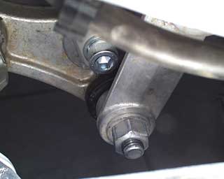
The bottom of the shock is installed using a new M10x52 Allen head bolt (M10x55 must be cut) with M10 washers and a locknut. The shock bolts can now be tightened. (30-35 ft/lbs.)
The swing arm linkage bolt can now be tightened to 53ft/lbs.
46
The threads for the rear wheel adjusters most now be extended using a 8mm die. by approx 10-15mm.
47
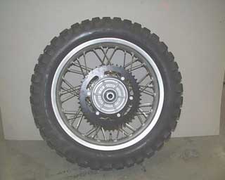
The rear sprocket carrier must be removed from the original rear wheel. Remove the six bolts (13mm wrench) that secure the sprocket to the carrier.
48
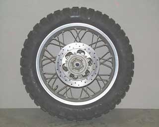
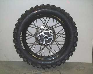
The six screws that secure the brake disc to the wheel are removed. The brake disc can now be installed on the new EXCEL wheel. The recesses in the disc for the bolts go toward the outside. Install the six bolts using Loctite 243, and tighten in a cross pattern to 7ft/lbs.
49
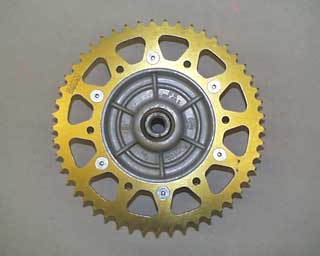
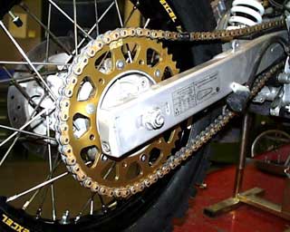
The new TALON sprocket is now installed onto the original carrier using six new M8x40 button head bolts, washers and lock nuts. The markings on the sprocket face outwards, and the bolts fit into the recessed holes. The bolts are tightened to 15ft/lbs.
50
The rubbers from the original rear wheel are installed into the hub of the EXCEL wheel and the sprocket carrier in installed.
51
The EXCEL wheel is installed with the original axle and nut. The new EXCEL chain is shortened to 117 links and connected using a special chain rivet tool. Adjust the tension of the chain so there is 30-40mm of play with the suspension in the unloaded position. Tighten the axle nut to 72ft/lbs.
52
Install the new aluminum chain guard, and caliper guard following the instructions included with the guards.
53
Remove the wiring cover (torx25) and cut the cable tie to the rear of the cover.
54
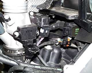
Disconnect the three plugs under the cover. Remove the ground cable (torx30) and the starter cable (10mm).
55
Remove the tiny screw that secures the throttle idle micro switch. (Phillips head).
Disconnect the plug for the oil pressure switch.
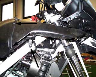
Remove the original shock reservoir mounting bracket and the voltage regulator. Save the sheet metal nuts, spacers and the rubber bushings.
56
Disassemble the intake.
Remove the plug from the temperature sensor. Remove the two screws and pull outward on the clip that connects the two halves of the air cleaner housing together. Pull outward on the intake and then back to remove.
57
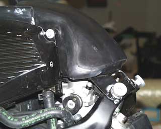
Remove the two large shoulder bolts (torx45) that secure the airbox to the frame and the (torx30) bolt that connects the oil tank to the airbox. Pay attention to the spacers. Lift up on the airbox to release it from the throttle body. Next remove the two screws on each side of the air cleaner mount cross member. (Torx30) Remove the cable ties, the plugs and the fuse box from the right side of the cross member. On the left side remove the clamp from the fuel pressure regulator/filter assembly. Now remove the cross member.
58
Disconnect the plugs from the throttle body, the actuator and the ignition coil.
Take off the two nuts that secure the battery box. The battery box with nuts and washers will be reused.
59
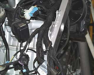
Pull the entire wiring harness upwards as it now needs to be rerouted on the top side of the motor mount. After the harness has been situated all the plugs can now be reconnected. If the harness is not rerouted the fuel pump wires will not be long enough. The plugs are all polarity safe, and cannot be plugged in incorrectly. (Without forcing them)
60
Assemble the new mounting bracket for the regulator and engine computer. The two pieces of the bracket are assembled using an M6x20 (1) countersunk bolt with washer and locking nut. This long bolt will also have a wire loop clamp (12mm) installed with an additional locknut. The second bolt M6x16 (2) is installed with a washer and locknut as well.